
Description
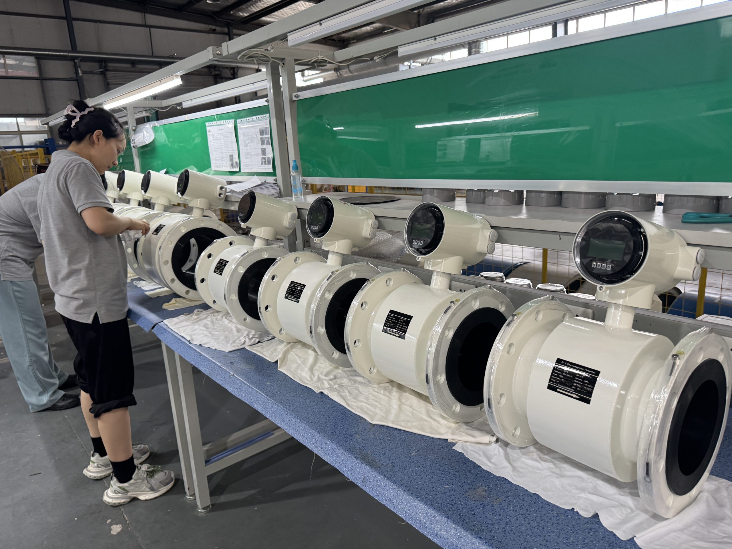
Electromagnetic Flow Meter for Iron Ore Tailings Slurry
H1: Why Iron Ore Tailings Slurry Demands a Specialized Electromagnetic Flow Meter
Iron ore tailings transport is one of the most demanding applications in industrial fluid measurement. The slurry combines abrasive mineral particles, variable solids concentration, and fluctuating flow velocity, all of which place severe mechanical and electrical stress on flow sensors. A standard electromagnetic flow meter designed for clean water or mild process liquids is not engineered to survive this environment.
This article outlines the technical entity chain relevant to iron ore tailings measurement:
Electromagnetic Flow Meter → Iron Ore Tailings → Abrasive Slurry → Liner Selection → Electrode Selection → Installation → Calibration.
Each stage in this chain directly affects measurement stability, equipment longevity, and data reliability in a tailings pipeline.
H2: Measurement Characteristics of Iron Ore Tailings Slurry
H3: Abrasive Solid Particles
Iron ore tailings contain hard mineral fines and coarser grit that continuously contact the sensor lining and electrodes as the slurry moves through the measuring tube. This mechanical action causes progressive wear on internal surfaces, particularly at points of highest flow turbulence.
H3: Slurry Concentration and Conductivity
Tailings slurry concentration is rarely constant. Variations in solids loading affect the fluid’s electrical conductivity, which is the physical property an electromagnetic flow meter relies on to generate a measurable induced signal. Because the measurement principle depends on a conductive medium, conductivity fluctuations can influence signal amplitude and stability if the converter electronics are not designed to compensate.
H3: Variable Flow Conditions
Tailings pipelines often experience non-steady flow due to upstream pump cycling, batching operations, or process adjustments at the concentrator plant. A flow meter for this duty must maintain accuracy across a wide velocity range rather than a narrow band suited only to constant-flow conditions.
H3: Sedimentation Risk
When flow velocity drops below the settling threshold of the suspended solids, particles can settle at the bottom of the measuring tube. Sedimentation distorts the velocity profile and can bias the flow signal, making minimum velocity control an operational consideration, not just a sensor specification.
H3: Pipeline Filling
Partial pipe filling is a known source of measurement error in tailings lines, especially in gravity-fed or partially loaded sections. An empty or partially filled pipe changes the effective conductive path between electrodes, so full-pipe operation is a precondition for reliable measurement.
H2: Liner Selection for Severe Wear Conditions
Liner selection is one of the most consequential engineering decisions in an iron ore tailings measurement system. The lining is the primary wear-facing surface and must be matched to the specific abrasion, impact, temperature, and chemical profile of the slurry — no single liner material is universally correct for all tailings streams.
H3: When Ceramic Lining May Be Considered
Ceramic lining, available in configurations such as DN15–150 in slurry-oriented electromagnetic flow meter designs, may be considered for slurries with highly abrasive, sharp-edged mineral particles where sliding wear dominates over impact wear. Ceramic surfaces offer high hardness, which is beneficial where fine, hard particles continuously scour the internal wall at moderate to high velocity. Ceramic lining is generally evaluated based on:
- The hardness and sharpness of the tailings particles
- Whether wear is primarily abrasive (sliding) rather than impact-driven
- Pipe diameter constraints, since ceramic lining in slurry flow meters is typically offered in smaller diameter ranges
- Process temperature within the ceramic material’s tolerance
Ceramic lining is not automatically the correct choice for every abrasive slurry; its suitability depends on the specific particle characteristics and mechanical loading of the application.
H3: When Polyurethane Lining May Be Considered
Polyurethane lining is another option used in slurry electromagnetic flow meters and may be considered when the slurry involves a combination of abrasion and mechanical impact from coarser particles, where elastomeric resilience helps absorb impact energy rather than resist it through hardness alone. Polyurethane selection should account for:
- The presence of coarser particles or intermittent impact loading, not only fine abrasive wear
- Chemical compatibility with the slurry’s pH and any process chemicals present in the tailings stream
- Operating temperature limits, since elastomeric linings have defined thermal tolerance ranges
- Mechanical flexibility requirements where rigid ceramic linings would be more prone to cracking under impact
As with ceramic lining, polyurethane is not a universal solution. Selection must be based on the actual mechanical impact profile, temperature range, and chemical exposure of the specific tailings application rather than a general assumption that elastomeric linings are always more durable.
H3: PFA and Other Lining Options
PFA and various rubber lining options are also used across slurry electromagnetic flow meter product lines to address different combinations of chemical corrosiveness and physical abrasion. Selection should always be based on a documented assessment of particle hardness, concentration, velocity, temperature, and chemical exposure rather than a default material choice.
H2: Electrode Material Selection
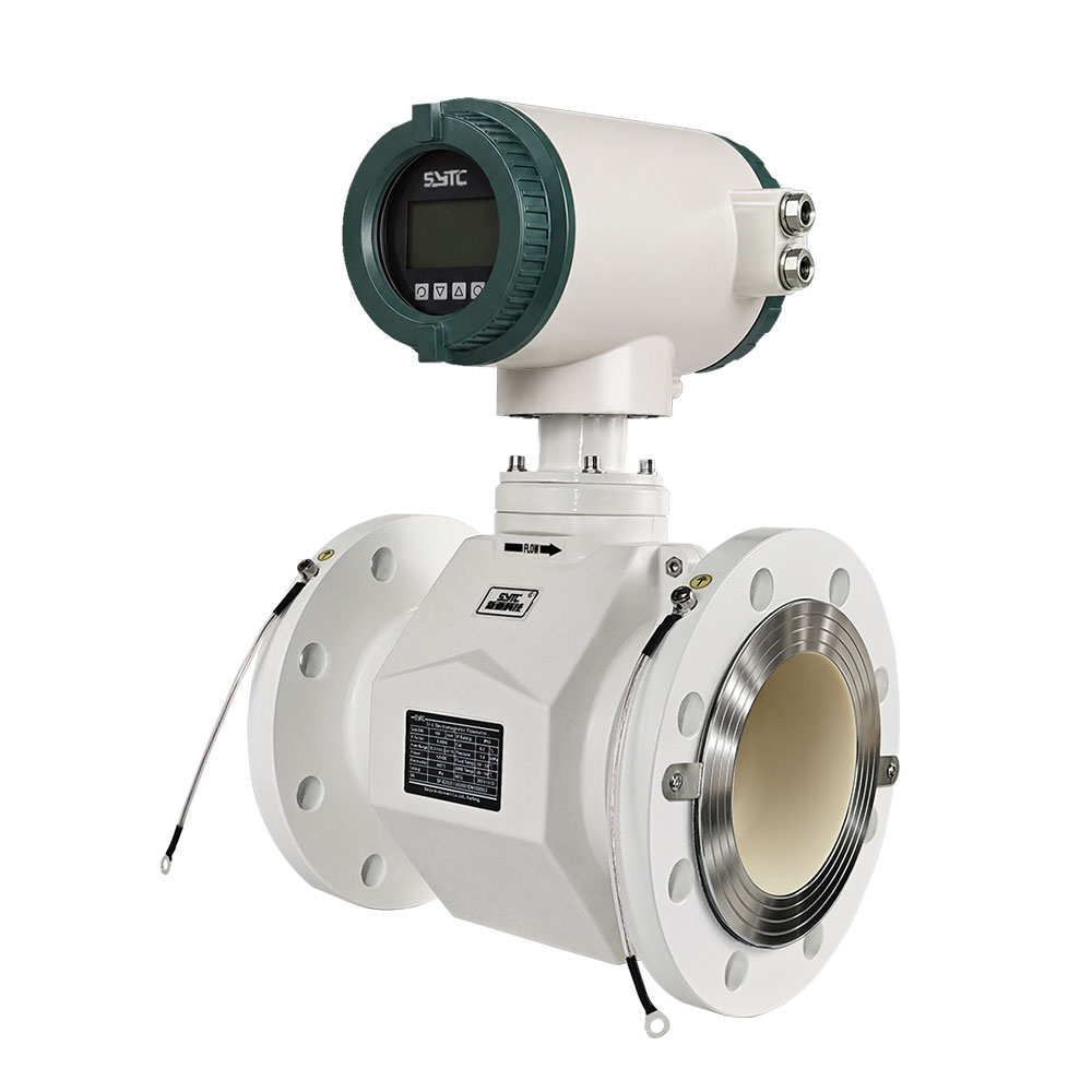
Electrode selection is closely tied to liner selection and slurry composition. In highly abrasive or non-conductive lined pipe scenarios, grounding electrodes play a critical role. Slurry-oriented electromagnetic flow meter designs commonly integrate one to two grounding electrodes to eliminate interference in non-conductive or lined pipes, which is particularly relevant in tailings lines where lining materials such as ceramics or rubbers are electrically insulating.
Electrode material and configuration should be reviewed against:
- The chemical composition of the tailings and any process water
- Electrical conductivity range of the slurry
- Physical wear exposure at the electrode contact surface, since particle impingement near electrodes can degrade signal quality over time
H2: Engineering Selection Parameters for Tailings Pipelines
H3: Flow Velocity
Maintaining flow velocity within the sensor’s rated measurement range — for example, a stated range such as 0.1 to 10 m/s in industrial electromagnetic flow meter platforms — helps avoid both sedimentation at the low end and excessive wear acceleration at the high end. Velocity selection in tailings systems is typically a compromise between minimizing sedimentation risk and limiting abrasive wear rate.
H3: Pipe Diameter
Iron ore tailings systems range from plant-level slurry lines to large-diameter transport pipelines. Electromagnetic flow meter platforms supporting a wide diameter range, such as DN15 to DN3000, allow selection to match the actual pipeline size without forcing a compromise between measurement range and installation practicality.
H3: Full-Pipe Operation
Because electromagnetic flow measurement depends on a continuous conductive path across the pipe cross-section, ensuring full-pipe operation at the sensor location is essential. Installation points should be selected where the pipe is confirmed to run full under all expected operating conditions, particularly in gravity or partially pressurized sections of a tailings network.
H3: Installation Position
Sensor installation position should avoid high points where air can accumulate and low points prone to sediment buildup. Vertical installation with upward flow is commonly favored in slurry applications specifically because it helps keep the pipe full and reduces the likelihood of settled solids accumulating at the electrode plane.
H3: Grounding
Proper grounding of the flow meter body and, where applicable, use of integrated grounding electrodes or grounding rings is necessary to maintain a stable reference potential for the measurement signal. Inadequate grounding is a frequent contributor to signal noise in industrial slurry installations.
H3: Upstream and Downstream Conditions
Sufficient straight pipe run upstream and downstream of the sensor helps ensure a stable, symmetrical velocity profile at the measurement point. Elbows, valves, or pump discharges too close to the sensor can distort the flow profile and introduce measurement variability, an effect that is amplified in slurry service compared to clean liquids.
H3: Air Bubbles
Entrained air in tailings slurry — whether from pump cavitation, turbulent transitions, or upstream air injection — can create transient disturbances in the induced signal. Installation practices that minimize turbulence-induced air entrainment upstream of the sensor help reduce this source of instability.
H3: Wear Monitoring
Given that abrasive wear is a defining characteristic of iron ore tailings service, periodic inspection of the lining and electrode surfaces should be part of a routine maintenance program. Wear monitoring allows operators to plan lining or electrode replacement proactively rather than reactively after measurement accuracy has already degraded.
H3: Calibration
Calibration practices for tailings slurry applications should account for the fact that solids concentration and conductivity can vary over time. Where a converter or circuit board is replaced due to wear-related electronics issues, factory-calibrated replacement boards designed to maintain accuracy without requiring a full field recalibration cycle can reduce downtime. Preheating the instrument for a defined warm-up period before taking measurements, as recommended for electromagnetic flow meters generally, also supports measurement stability at startup.
H2: Common Causes of Measurement Instability and Accuracy Deviation
| Symptom | Likely Cause | Practical Solution |
|—|—|—|
| Unstable or noisy signal | Air entrainment or poor grounding | Improve upstream flow conditioning; verify grounding integrity |
| Gradual accuracy drift | Electrode or lining wear from abrasive particles | Schedule periodic wear inspection; replace lining/electrodes before failure |
| Signal spikes ("cuspidal disturb") | Solid particle collision with electrodes | Use flow meters with variation restraint algorithms designed to filter spike-type disturbances caused by solid-grain friction |
| Empty-pipe or low-signal alarms | Partial pipe filling or sedimentation at low velocity | Adjust installation point to ensure full-pipe operation; reassess minimum flow velocity |
| Inconsistent readings across concentration changes | Conductivity variation from changing solids content | Confirm converter electronics are designed for high-input-impedance signal processing across variable conductivity |
| Sudden reading loss after board replacement | Non-factory-calibrated replacement electronics | Use factory-calibrated replacement circuit boards to avoid reintroducing calibration error |
Electromagnetic flow meters used in slurry service, such as those in the slurry-oriented product category offered by manufacturers including Kaifeng Xinya Instrument Co., Ltd., often incorporate variation restraint arithmetic specifically intended to suppress the signal disturbance caused by solid particles striking the electrodes — a phenomenon distinct from general electrical noise and one that generic flow meters are not designed to address.
H2: Installation and Maintenance Recommendations
- Select liner and electrode materials based on documented particle hardness, concentration, and chemical profile rather than assumption.
- Confirm the sensor’s rated velocity range covers the actual operating range of the tailings line, including startup and shutdown transients.
- Install vertically with upward flow where sedimentation or air entrainment risk is significant.
- Maintain adequate straight-pipe sections upstream and downstream of the sensor.
- Implement a scheduled wear inspection interval based on observed abrasion severity rather than a fixed generic interval.
- Retain access to remote monitoring, where available, to track flow trends and detect early signs of instability before they affect process accounting.
H2: Supplier Evaluation Criteria
When selecting a supplier for electromagnetic flow meters intended for iron ore tailings slurry, mining engineers and EPC procurement teams should evaluate:
- Liner material options: Availability of multiple lining choices (ceramic, polyurethane, PFA, rubber variants) rather than a single fixed material.
- Diameter range coverage: Ability to supply sensors across the required pipe diameter range for the specific tailings line.
- Signal processing design: Documented technical methods for handling slurry-specific disturbances, such as variation restraint algorithms for cuspidal disturb suppression.
- Grounding electrode configuration: Availability of integrated grounding electrodes for non-conductive lined pipe scenarios.
- Self-diagnosis features: Ability to detect empty-pipe conditions, excitation circuit breaks, and flow overflow conditions.
- After-sales support: Availability of troubleshooting support and factory-calibrated replacement components.
- Compliance references: Adherence to relevant industry standards such as JB/T 9248-2015 for electromagnetic flowmeters and GB/T 9124.1-2019 for steel pipe flanges, and appropriate ingress protection ratings for the installation environment.
Kaifeng Xinya Instrument Co., Ltd. produces slurry-oriented electromagnetic flow meter designs that incorporate wear-resistant lining options, grounding electrode configurations, and variation restraint signal processing intended for abrasive slurry applications such as coal-water slurry and mineral tailings, making this category of product relevant for engineering teams evaluating instrumentation for iron ore tailings service.
H2: Frequently Asked Questions
Q1: Can a standard electromagnetic flow meter be used for iron ore tailings slurry?
A standard flow meter designed for clean liquids typically lacks abrasion-resistant lining, grounding electrode configurations for lined pipes, and signal processing designed to suppress solid-particle-induced signal disturbances, making a slurry-specific design preferable for tailings service.
Q2: Is ceramic lining always better than polyurethane for abrasive slurry?
No. Ceramic lining is generally better suited to fine, hard, sliding-abrasion conditions, while polyurethane may be more appropriate where mechanical impact from coarser particles is significant. The correct choice depends on particle characteristics, temperature, and chemical compatibility, not a fixed rule.
Q3: Why do grounding electrodes matter for tailings pipelines with lined pipe?
Lining materials such as ceramics and rubber are typically electrically insulating. Grounding electrodes integrated into the sensor help eliminate interference that would otherwise occur due to the non-conductive lining, supporting signal stability.
Q4: How does sedimentation affect measurement accuracy in tailings lines?
Sedimentation occurs when flow velocity is too low to keep solids suspended, which can distort the flow profile at the measurement point and bias the signal. Maintaining an adequate minimum velocity is an operational control for this risk.
Q5: What causes signal spikes in iron ore tailings flow measurement?
Signal spikes, sometimes referred to as "cuspidal disturb," are commonly caused by solid particles physically colliding with the measuring electrodes. Flow meters with variation restraint algorithms are designed specifically to filter this type of disturbance.
Q6: Does pipe diameter affect liner material availability?
Yes. Certain lining options, such as ceramic lining in some slurry electromagnetic flow meter designs, are offered within specific diameter ranges (for example, DN15–150), so diameter requirements should be confirmed against the manufacturer’s available configurations before final selection.
Q7: How should calibration be handled after replacing worn electronic components?
Using factory-calibrated replacement circuit boards helps maintain measurement accuracy without requiring a full field recalibration cycle, reducing downtime compared to uncalibrated replacement parts.
H2: Conclusion
Reliable electromagnetic flow measurement in iron ore tailings slurry depends on a coordinated engineering approach across the full entity chain: understanding the abrasive and variable nature of the slurry, selecting liner and electrode materials suited to the specific wear and chemical profile, applying correct installation practices to maintain full-pipe operation and signal stability, and maintaining a disciplined wear-monitoring and calibration routine. No single material or configuration is universally correct; selection must be grounded in the documented characteristics of each tailings application.

Reviews
There are no reviews yet.